
Views: 0 Author: Site Editor Publish Time: 2026-10-31 Origin: Site


Injection molding downtime drains profitability at an alarming rate. When a mold crashes or consistently produces defective parts due to subtle misalignments, the financial impact hits the production floor immediately. Uneven wear on mold guide pins is a notorious mechanical issue plaguing many facilities. While swapping out damaged hardware for fresh steel and restarting the press feels tempting, skipping the root-cause diagnosis guarantees those replacement parts will suffer the exact same fate.
In this comprehensive troubleshooting guide, we walk you through exactly what to inspect, measure, and correct before installing new mould components. By treating the symptoms rather than just replacing the parts, you protect your tooling investment and maximize production uptime.
Uneven wear on alignment hardware is rarely an isolated incident. It typically signals underlying mechanical misalignments, severe thermal imbalances, or catastrophic lubrication failures.
Installing brand-new pins into worn, out-of-round guide bushings accelerates degradation, locking you into a costly cycle of tooling failure.
Systematic verification of injection machine platen parallelism and mold cooling efficiency is a mandatory step in any pre-replacement diagnostic process.
Sourcing high-quality, precision-machined replacement components prevents premature friction and significantly reduces the risk of part defects like parting line mismatch or flash.
Within the complex kinematic sequence of an injection molding cycle, guide pins—frequently referred to in the shop as leader pins—serve as the primary macro-alignment mechanism between the core and cavity halves. Long before intricate shut-offs, side actions, or delicate core pins engage, these leader pins enter their corresponding bushings to ensure the two massive halves of the tool are perfectly concentric.
Their structural integrity ultimately dictates the operational health of the entire mold assembly. If these pins deflect, wear asymmetrically, or fail to glide smoothly, the core and cavity meet at a slight offset. Even a deviation of a few hundredths of a millimeter transfers immense lateral stress to other fragile components. Because they act as the first line of defense against lateral shifting during high-pressure clamping, maintaining their precise cylindrical geometry and flawless surface finish is critical to preserving the tool's lifespan.
Operators and maintenance engineers must rely on empirical evidence to spot abnormal wear patterns before they escalate into catastrophic tooling crashes. Fortunately, uneven wear rarely happens overnight. It leaves distinct mechanical, visual, and acoustic signatures a trained eye can catch early.
The most immediate evidence of asymmetric friction is found through routine visual inspection on the bench. Technicians should look for localized polishing, occurring when friction disproportionately attacks only one quadrant of the pin. As this condition deteriorates, localized friction generates heat exceeding the yield strength of the surface material, leading to galling. Galling is a severe form of adhesive wear where microscopic asperities on the pin and bushing weld together under high pressure, only to be violently torn apart as the mold opens. If you run a fingernail across the steel and feel deep, stepped scratches or notice metal flakes clinging to the grease on one specific side, lateral misalignment is virtually guaranteed.
Hardware degradation directly correlates with specific dimensional and cosmetic defects in the molded plastic parts. When pins wear unevenly, the mold halves inevitably shift under the immense pressure of molten polymer.
Flash: Worn pins allow the mold halves to shift laterally, creating micro-gaps at the parting line where low-viscosity polymer escapes. This flash is typically concentrated on one specific side of the mold perimeter.
Parting Line Mismatch: The core and cavity fail to align concentrically, causing a physical step or sharp ridge along the part's parting line. Caliper measurements often reveal asymmetrical wall thicknesses.
Dimensional Variation: A lack of rigid alignment allows the core block to deflect, altering the internal dimensions of the cavity and causing Process Capability Cpk values to drop unpredictably.
Acoustic monitoring remains a practical, non-destructive diagnostic tool. A healthy mold operates with a smooth, rhythmic hum during the opening and closing strokes. Grinding, squeaking, or sudden popping noises as the mold halves separate are immediate red flags. They indicate kinetic energy converting into destructive friction.
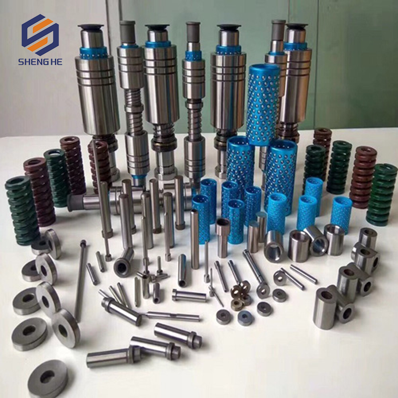
Industry Trend Analysis: Recently, the broader injection molding sector has witnessed a paradigm shift regarding tool longevity. Market data indicates a rapid transition away from reactive maintenance toward precision-driven preventative strategies. With molding tolerances tightening across automotive and medical sectors, facilities are increasingly integrating advanced IoT acoustic sensors to detect microscopic friction spikes long before physical galling appears. Furthermore, industry analysts note that upgrading to ultra-precise ground plates and hardware inherently reduces baseline lateral wear by up to forty percent, fundamentally shifting how toolrooms approach component lifecycles.
Replacing a galled component without addressing the underlying physics that caused the damage is an inefficient and expensive maintenance strategy. Uneven wear is almost always a symptom of one or more specific root causes.
Often, the injection molding machine itself is the culprit rather than the tool. If the stationary and moving platens are not perfectly parallel, the mold halves approach each other at a slight angle. This is frequently caused by uneven tie bar stretch, a sagging moving platen common on heavy molds lacking proper shoe support, or worn toggle linkages. Consequently, the guide pins are forced to muscle the heavy mold halves into alignment, subjecting them to severe side-load stresses they were never engineered to withstand.
Operating under high-friction, high-cycle conditions, alignment hardware relies entirely on a hydrodynamic boundary layer of lubrication to prevent metal-on-metal contact. If maintenance teams utilize the wrong type of grease—like a general-purpose lithium grease with a low dropping point that melts away at operating temperatures—this protective barrier evaporates. Furthermore, over-greasing traps abrasive airborne silica and polymer off-gassing residues. This contaminated sludge essentially turns into a lapping compound, slowly grinding away the steel's micro-finish.
Tool steel expands when exposed to heat. The coefficient of thermal expansion dictates that even a minor temperature variance across a large mold base causes measurable dimensional shifts. For example, if a blocked cooling channel causes the fixed half to run at 85 degrees Celsius while the moving half remains at 40 degrees Celsius, the two halves expand at drastically different rates. This differential expansion shifts the centerlines of the pins relative to their bushings, forcing them to bind aggressively during mold close.
Injection pressures easily exceed 20,000 PSI inside the cavity. If the mold base plates lack sufficient thickness or rigidity, this internal pressure forces the plates to bow outward in a phenomenon known as platen wrapping. When the plates deflect elastically, the guide pins bend slightly with them. Over hundreds of thousands of cycles, this repeated bending stress causes the hardware to rub aggressively against the hard edges of the bushings, leading to rapid deterioration.
To break the cycle of premature component failure, maintenance engineers must execute a rigorous, data-driven inspection protocol before a single new pin is hammered into place.
A fundamental rule of toolmaking is to never replace a worn pin without thoroughly evaluating its mating bushing. If a pin has worn asymmetrically, it has inevitably carved an elliptical or oval shape into the softer bronze or steel bushing. Inserting a perfectly cylindrical new pin into an oval bushing concentrates all contact stresses onto two microscopic points. Use a precision bore gauge or an inside micrometer to check for out-of-roundness. If ovality exceeds acceptable tolerances, scrap the bushing simultaneously.
Before blaming the toolmaker, verify the press. Mount a magnetic base dial indicator to the stationary platen and sweep the machined face of the moving platen across all four corners. The measurements should fall strictly within the machine manufacturer's specified tolerances. If the platens are out of parallel, the machine requires leveling, tie-bar calibration, or wear-pad adjustment before the mold is re-hung.
Investigate the thermal dynamics of the tool during an active production run. Utilize a flow meter to check all cooling channels for calcium scale buildup, rust, or blockages. Measure the temperature delta between the core and cavity halves using a thermal imaging camera. Ensuring that thermal expansion mismatch isn't the hidden force driving the pins out of alignment is a critical diagnostic step.
The alignment of your hardware is only as accurate as the steel plates they are mounted in. If the base plates have warped due to historical overheating, or if they were poorly machined from the start, the pins will sit at a permanent angle. Use a precision straight edge and feeler gauges to verify flatness. If the foundation is fundamentally flawed, upgrading to a high-quality precision ground mould plate is the only way to guarantee the new pins remain perfectly perpendicular to the parting line.
Treating uneven guide pin wear as a minor nuisance is a dangerous financial oversight. Because these pins dictate the macro-alignment of the entire tool, their failure triggers a cascading ripple effect that destroys other highly sensitive components.
When the mold halves shift laterally, precision interlocks bear the brunt of the misalignment, leading to rapid galling of the expensive tool steel. In severe cases, the core and cavity blocks may collide, causing edge crushing that requires micro-welding and costly CNC re-machining to repair. Internally, the shifted centerlines place excessive shear stress on ejector pins, return pins, and lifter mechanisms. What begins as a simple alignment issue quickly escalates into a massive overhaul, necessitating the replacement of multiple mould accessories and resulting in weeks of unplanned production downtime.
Once the root cause is identified and corrected, selecting the appropriate replacement parts becomes the next critical engineering decision. Installing substandard hardware simply restarts the cycle of premature failure. To make this actionable on the shop floor, we must look at concrete metallurgical properties.
The metallurgical properties of the replacement pins dictate their longevity. Standard guide pins operate under extreme mechanical stress, requiring a delicate balance between surface hardness and core toughness. Industry-standard materials supplied by top-tier manufacturers typically include high-grade bearing steels like SUJ2 or cold-work tool steels like SKD11. The ideal pin features a case-hardened surface—often reaching 58 to 62 HRC—for maximum abrasion resistance. Meanwhile, the core remains slightly ductile around 35 to 40 HRC to absorb lateral shocks without snapping.
For high-volume production environments or medical cleanrooms where liquid lubrication must be minimized, bare steel is often insufficient. Advanced surface coatings applied via Physical Vapor Deposition significantly alter the tribological properties of the pins. Coatings like Titanium Nitride or Diamond-Like Carbon drastically reduce the coefficient of friction and provide self-lubricating properties, offering an extra layer of defense against galling.
The most advanced materials are rendered useless if the dimensional tolerances are inconsistent. Guide pins and bushings rely on precise clearance fits measured in micrometers. It is imperative to partner with a reliable supplier that utilizes precision centerless grinding and rigorous Coordinate Measuring Machine inspections. For example, high-end components maintain a concentricity and dimensional tolerance within 0.002mm to 0.005mm. Investing in premium components ensures the replacement parts perform predictably under the harsh conditions of continuous injection molding.
Component Feature | Standard Market Hardware | Precision Ground Components |
|---|---|---|
Material Grade | Basic carbon steel | Premium SUJ2 / SKD11 Tool Steel |
Surface Hardness | 45-50 HRC | Case-hardened 58-62 HRC |
Dimensional Tolerance | ± 0.02 mm | Within 0.002 mm - 0.005 mm |
Wear Resistance | Prone to rapid galling under side-load | High abrasion resistance, supports high-cycle runs |
To protect your newly installed components, shift your focus to a strict, data-driven preventative maintenance schedule. A reactive strategy—waiting for defects to appear—inevitably leads to accelerated wear.
Maintenance intervals should never be based on arbitrary calendar days. They must be dictated by the shot count and the type of resin being processed. For standard operations, pins should be wiped down and re-lubricated every 20,000 to 50,000 shots. Molds running high-temperature engineering resins or materials that produce heavy off-gassing like PVC may require servicing every 10,000 shots.
When cleaning, technicians must use safe, non-corrosive solvents that dissolve degraded grease without leaving a residue. Avoid abrasive cleaning pads like Scotch-Brite or sandpaper, as these destroy the micro-finish of the steel and strip away protective coatings. Finally, apply only specified high-temperature, high-pressure mold grease infused with PTFE or molybdenum disulfide. Apply it sparingly. A thin, translucent film is far more effective than heavy clumps, which only serve to attract abrasive debris and cause hydraulic lock inside blind bushing holes.
Yes, it is highly recommended by tooling engineers. Guide pins and bushings are mating surfaces that wear into each other over time. If a pin exhibits uneven wear, the corresponding bushing has likely deformed into an oval shape or sustained internal scoring. Inserting a perfectly cylindrical new pin into a damaged, out-of-round bushing creates uneven contact points, causing the new pin to degrade rapidly. Replacing them as a matched set ensures proper clearance and extends the life of the tooling.
Lubrication frequency depends heavily on the mold's cycle time, operating temperature, and the specific material being molded. As a general baseline, pins should be cleaned and re-lubricated every 20,000 to 50,000 shots. However, molds running high-temperature resins or materials that produce heavy off-gassing may require lubrication every 10,000 shots. Conversely, molds utilizing coated pins in medical cleanrooms may run completely dry or require specialized, minimal-application synthetic lubricants at much longer intervals.
Absolutely. Guide pins are the primary mechanism keeping the core and cavity halves aligned against the immense injection pressure. If the pins wear unevenly, the mold halves can shift laterally or fail to close perfectly parallel. This misalignment creates microscopic gaps at the parting line. When the molten plastic is injected, it follows the path of least resistance and flows into these gaps, resulting in flash. Fixing the alignment hardware is often the very first step in troubleshooting flash defects.
The optimal material is typically a high-quality bearing steel like SUJ2 or a cold-work tool steel like SKD11. The critical factor is not just the base alloy, but the heat treatment process. The best pins are case-hardened, meaning they possess an extremely hard, wear-resistant outer surface around 58 to 62 HRC to prevent scratching and galling, combined with a tougher, more ductile inner core that can absorb mechanical shocks without fracturing.
To verify platen alignment, technicians should mount a magnetic base dial indicator to the stationary platen of the injection press. By sweeping the machined face of the moving platen across all four corners, you can measure any deviation. If the readings fall outside the machine manufacturer's specified tolerances, the tie bars require recalibration or the wear pads need adjustment before installing the mold back into the press.
Galling is a severe form of adhesive wear caused by excessive friction and heat. When a pin and bushing are misaligned or inadequately lubricated, the metal surfaces rub together under extreme pressure. This friction generates enough localized heat to exceed the material's yield strength, causing microscopic asperities on the steel to weld together and tear apart during the mold opening stroke.
Mold guide pins are the unsung heroes of precise tooling alignment. When they begin to exhibit uneven wear, they are acting as a mechanical alarm bell, signaling deeper platen misalignments, thermal warpage, or severe lubrication breakdowns. Always take the time to inspect your equipment, measure your bushings, and verify your cooling channels before hammering in replacement parts.
By finding and correcting the root cause, you prevent repeated failures and break the cycle of unplanned downtime. Follow a strict, shot-count-based maintenance schedule, and always select premium, precision-ground components to maintain your production efficiency. Proactive care and diagnostic diligence are the ultimate keys to reducing costly part defects and extending the life of your valuable injection molds. For facilities looking to upgrade their tooling reliability, exploring the rigorous standards of Shenghe Steel ensures you are building your molds on a foundation of uncompromising precision.


